Friday 30 December 2011

Build day 22


Build time today 0.5 hours - Total build time 67.0 hours.
 Man time today 1.0 hours - Total man time 80.5 hours.


The time does not include running around. 
Picked up the engine crane at lunch time then popped to the local Staples to get a couple of paint pens to mark up torqued nuts and bolts. Once home I spotted that there was not chain or anything with the crane so gave them a quick ring, they explained that it does not come with anything else and when he had hired them in the past people had coped. He did say that he did have some heavy duty chains though used to support waist shoots and a 1 ton webbed support strap. Back to the hire shop to collect from the helpful HSS staff.


Oli explaining to Becki how the hoist works.
Now to lower the car from its stands. The plan was to use the hoist to lower the rear while Oli and I lowered the front, we therefore needed an extra pair of hands, Becki came to help with the task of leasing the hoist down. The front of the car was heavier than expected but nevertheless it got lowered. Part of the problem was access, Oli stood in the engine area while I stood at the very front. Once the supports were out of the way we lowered it a quickly and safely as possible.


Car lowered to ground


Once lowered there was a little playing and imagination. Then we tried to adjust the front track as there looks to be too much toe out, even fully adjusted it does not look correct. 


Brrooom Brroooom


Done for the day and ready to have a go at the engine tomorrow (new years eve) need to stop now as we have a family party later.

Build Day 21


Build time today 1.5 hours - Total build time 66.5 hours.
 Man time today 1.5 hours - Total man time 79.5 hours.

Managed to spend an hour or so preparing for the engine installation. Needed to get the prop shaft installed before the engine is fitted. Quite a straightforward task. I used a cable tie to support the gearbox end while I fastened the other to the diff.  I did a bit more fiddling with the handbrake while I was at it and that seems to be working much better. It now pulls up four clicks and holds the wheels firmly in position. To tighten the bolts into the diff I lined each one up just off top dead centre and used an extension bar on the torque wrench to tighten each up before rotating the wheel to move the next bolt hole into position. 

Once completed I considered the engine install and looked for any relevant nuts and bolts. There is no Zetec specific engine installation instructions, so I looked through the 1600i and sport 2000 instructions supplied. there is an mounting plate that goes on the left hand side, found the plate easily enough but it says that it needs to be fastened with 25mm M8 hex nuts and bolts, and I could not find any, found some M10s but not M8s. for the moment the plat is held loosely with M8 Allen key bolts, that are too long. Will have to add them to the list of questions for the factory when it re-opens in the new year.
As we will be lowering the car to the ground  I put on the wheels on, it is looking more and more car like, once the engine is installed I will put the car on axle stands and take them off again.

I guess we are as ready as we can be for the engine installation, picking up the engine hoist tomorrow.


Saturday 24 December 2011

Build Day 20


Build time today 2.0 hours - Total build time 65.0 hours.
Man time today 2.0 hours - Total man time 78.0 hours.

Got another couple of hours in today, it is Christmas Eve. 

Finished off the fuel system at the rear, re routed the pipe from the tank to the pump so that it is well away from the brake pipes then fitted the return feed. 


The next thing to do is fit the speed sensor. According to the guide there are two types, VDO and Smith white faced. Out with the box containing the gauges, they are black faced but don't appear to be VDO and the sensor looks more like the one in the Smiths picture and fitting instructions. The VDO fits to a bracket by the right diff output the Smiths a bracket by the right front brake disk. The unit is too small to fit in the hole by the diff supporting the theory it isn't VDO. Trouble is I can't find a bracket to fit by the front right brake disc either. Never mind put every thing back in the box. I will have to confirm with the factory in the new year.

Now on the top searing column, instructions very straight forward, basically it should involve put in place and bolting top and bottom. Not quite so easy in practice as there is no hole in the foot well panel. I got the column lined up as best as I could and marked the centre point, I then drilled a small hole from the inside and then using a 38mm hole saw (smallest I had that was bigger than the required 32mm for the column) I then drilled back at, what I hoped was, the correct angle. Then after filling the rough edges fitted the column. I soon realised that the bolts I had were not quite the correct length, a quick look at the steering rack confirmed I had used the wrong ones there. I guess I used ones that were too long as I had trouble getting them to fit and needed as much length as possible to get the nut to bite on the bolt. I quickly swapped them and re-torqued the steering rack. Now just to tighten them up on the column. For the moment I had got them just tight enough to hold it in place, there is quite a bit of movement and I will tighten once I am sure the column is correctly positioned.


Just the water bottle to fit and prop shaft before the engine goes in, these can wait otherwise I'll have nothing to do. The engine crane has been booked for next weekend. I did a bit of tidying before finishing for the day taking time to vacuum up the bits from inside the car.

Build Day 19


Build time today 2.0 hours - Total build time 63.0 hours.
Man time today 2.0 hours - Total man time 76.0 hours.

Fuel filter mounted
(it does not touch the diff)
A few more hours on the fuel system, got the fuel filter and fuel pump attached. The build guide is a little vague  as to exactly where to attach, it gives a general indication but no specifics, so after much pondering I finally decided on the exact locations. Can't say it was easy marking and drilling the chassis from underneath. Could have done with creating the mounting holes when the car was upside down or on its side. There is no chance of moving the car now as the rear is heavy, I suspect I will need to lower using the engine crane. Nevertheless the filter and pump were mounted after a bit of fiddling and perseverance.
Fuel pump mounted


Next to attach the pipes the guide says to use spiral wrap where the pipes can touch the frame as there isn't any large enough for the 1/2" pipe I had to improvise. I knew I had some caravan waste pipe somewhere from my Caravanning days (Yes I know, caravans, bane of everyone's life, hold you up pottering down the road, I doubt you ever got stuck be hind me though, I was normally stuck behind some one else pottering down the road, and where possible I would leave a gap between me and the car in front to allow faster cars to pass.) Once found it was simple to cut it down its length turning it into a protective wrap. I will probably need to change the routing a little, the main pipe from the tank to the pump is not correct and needs to miss the fuel line. I guess it will all need to be reviewed again once on it's wheels.
View of pump and filter

Main fuel line from tank to pump
Needs to be changed to miss the brake line


Need to get a hoist ordered tomorrow as I now realize I am running out of pre-engine tasks.


Friday 23 December 2011

Buid Day 18


Build time today 2.0 hours - Total build time 61.0 hours.
Man time today 2.0 hours - Total man time 74.0 hours.

An evening spent on the fuel system at the rear of the car.

4" bolt in rear mounting that is too short
Firstly I had managed to pop in to Westfield to get a couple of 4" bolts that the build guide says are needed to fix the tank mounting bracket to the top wishbone mounts. Even that was a close call as they were stock taking and would not be supplying/shipping anything until the new year, they did supply the bolts thought thankfully.

I swapped my inserting a shorter bolt in the nut end to push the existing bolt out then pushing the new longer ones back the other way, therefore keeping everything lined up. Did the front bolts first and they fitted a treat but to my horror when I changed the rears they were a little too short, meaning the thread lock on the lock nut would not catch. Fantastic I thought I need to try and pop in tomorrow and hope I can get a couple of 4 1/4" bolts with the hope that I could get there before they closed and that they would swap them if the stock check was still going on. Never mind must carry on and if necessary I can swap at a latter date.

4" bolt in front mounting looks long enough to me
I then proceeded to locate more of the fuel system components: - tank; tank straps; fuel pump; fuel filter; various pipes brackets and clamps. Reading the guide it says that the tank straps and frame need some sticky backed foam applying, so I hunted for and found it in the box I had put items that I considered would be needed much later on: wing mirrors, screen mountings, wipers, IVA kit etc  Also in the bag were some long bolts 4 1/2" plus the correct number of M6 nuts, bolts and washers for the tank straps. One of the real issues is correctly identifying which bags of parts are for what purpose. I know they are working on improving this and for future builders it should make the process less frustrating. Quickly swapped the 4" bolts for the 4 1/2" and issue sorted.


4 1/2" bolt in rear mounting 
Fuel tank fitted


Right now on to fitting the tank I now had all the parts assemble, I think, and ready. Fitting the tank was not too difficult. Just needed to line up the tank straps and drill 6 mm holes in the appropriate places. I just lined them up so that they would fit in such a way that then end of the strap lined up with the bottom of the mounting bracket. The bolts at the rear are pre attached to the frame so it is just a matter of lining up by feel getting the front bolts through and getting the nuts to catch is more difficult as there is quite a gap and it would have been useful to have an extra pair of hands. Oli was out so I persevered with a clamp and pair of mole grips. At last a fitted tank.

Fuel system components assembled ready for fitting
I then started to assemble the remaining bits reading and re-reading the guide until clear what needs to be done. I managed to get the rubber cover over the fuel pump after several attempts and liberal use of spit on the inside.
Fitting the filter and pump are next. More chassis drilling required to mount them on the underside of the car. Glad the car is still on the stands though I expect it is getting heavy and may be difficult to lower to the ground. Guess I may be able to use the Engine Crane, when hired perhaps next weekend, to assist with lowering.

Wednesday 21 December 2011

Build Day 17


Build time today 2.5 hours - Total build time 59.0 hours.
Man time today 2.5 hours - Total man time 72.0 hours.


Evening of bits and bobs, started by finishing off the top scuttle panel area and preparing for the footrest in the passenger foot well. Completed the rivet nut insertion, if there is a knack to inserting rivet nuts I'm not sure I have it yet as I managed to bend another rivet nut mandrel, better order another spare. Though when fitting the 5mm aluminium rivet nuts for the foot brace they seemed to go in much easier.


Next I cable ties the wiring at the rear of the car and part way down the tunnel, followed by the slow task of filling the differential with oil, Becki popped into Halfords for me and purchased a funnel with a flexible neck which helped considerably. Not knowing how much oil to add makes it a little difficult so I arranged some plastic and used one of the protective plastic ends that I had removed from the drive shafts to catch any spillage. Once oil started to poor at the filling hole I stopped and put the plug back in. It took quite a while to poor in, must check to see how much is expected to go in.

Next attached the hand brake cables to the callipers, with a couple of 5mm bolts and lock nuts. Still not convinced all is correct with the hand brake.


Now at last back on to the fuel supply. First attached and wired up the inertia switch, says to use a couple of M5x16mm bolts and lock nuts, couldn't find any so used a couple that I already had.

Now on to the tank. I remember seeing something in the FW body work section an the tank so its time to use the two guides again. The tank in the FW fits over the dif on a special tray attached to the upper wish bone mounts. It says I need to replace the standard bolts with 4" bolts, I know I haven't got any as I needed a couple to fit the upper wishbone to the upright and had to collect a couple from the factory. Looks like another visit before Christmas or I'll be a little stuck for a while. Still I took the nuts off and pulled the bolts back a little so I could get the tray in place. Just need to swap the bolts for the longer ones and re-attach the nuts, which won't take long.
Put the tank in place to see how it fits, quite straightforward, but I'll call it a night and leave it there.


Build Day 16


Build time today 5.0 hours - Total build time 56.5 hours.
Man time today 5.0 hours - Total man time 69.5 hours.

Started by getting all the wiring back in place. I have not attached with cable ties yet as I am sure I will need to adjust, especially at the front of the car as there is still more loom to be attached. For the moment I have just taped the wires in place.


upright supported and wishbone and shoke
held out of way ready for drive shaft to
be installed
Next on to fitting the drive shafts.
To make it easier to access I removed the top upright mountings and allowed the upright to rest on a trestle. I held the shock and top wishbone out of the way with a piece of string.
Getting the drive shaft lined up and the bolts in is a little fiddly, I had a couple in at each end when I remembered they needed to be lock tighted so had to take some of the bolts back out. Once all were in place and loosely tightened I torqued them all up to the correct setting. I have purchased a set of Allen keys with a 1/2" adapter so that I can now torque up Allen key bolts.
To get at each bolt I had to turn the drive shaft using a metal poll placed between the wheel bolts.
Once both drive shafts were installed I reattached the upright and then torqued all the nuts and bolts up to about 15lb/foot, they will need to be correctly set once the car its wheels and correctly set-up.
With the uprights now in place I attached the rear brakes and did some more work on the hand brake. there is not too much in the guide on attaching and adjusting the hand brake. There is no mention of what to attach the hand brake cable to the rear brakes with, my assumption is to use a cotter pin and split pin but can't find any so am not sure. ( since confirmed with factory to use not and bolt).
Right Drive Shaft in place
Left Drive Shaft in place


Its starting to look more like a car


Had to stop to do some DIY for my Mon and Dad, life needs to go on.
It is starting to look more like a car now.
I should be starting on the fuel system components next, inertia switch, tank, pump etc. It won't be long before the engine goes in. For that I need to hire/borrow and engine hoist, hopefully it should go in over the Christmas holiday.

Saturday 17 December 2011

Build Day 15


Build time today 5.0 hours - Total build time 51.5 hours.
Man time today 7.0 hours - Total man time 64.5 hours.

Now I have the missing lock nuts I started by completing the steering rack. Had a slight hitch but having spoke to someone at the factory they pointed me in the correct direction. Started with the left side and had no issues, but with the right hand side when I tried to tighten down the steering arm the the track rod end the rod pin just kept turning the left had tightened without doing anything. The factory said that the rod pin needed to be held and recommended turning the turning the track rod end with a spanner so that it gripped the rod pin allowing the nut to be tighten on. With the pin held it went on without any trouble. leaving 5 threads exposed on the track rod end meant that the front wheels look to have too much toe out so I reduced it to 4 threads, still looks to be to much but I will leave any further adjustment until it is sitting on wheels.


Then back on the fitting the wiring loom, I firstly attached the fuse holders, I had marked up the wires as directed but when I started to detach them I realized that they were individual wires and I had only marked one side, this meant that it would be easy to mix up the some of the wires. I stopped detaching and market up both side. As I had detached a couple of wires that were not marked I will contact the factory to confirm that I have them in the correct order. Once fasted I then proceeded to put the wires that fit behind the dash through the second hole in the top scuttle panel. I started with the wires furthest from the grommet but got stuck when it came to put through the relay units as they would not fit through. I had to pull the wires back through and push the relays through first. This method worked OK and the top scuttle panel is not in position but not yet attached.


Top scuttle panel in place
(not attached though)
Fuses attached and relays pushed through ready for
the rest of the dash wiring


Differential in place.
What an effort
Now back to fitting the diff. This is a two man job and I was assisted by Oli. Not an easy task getting the holes lined up and washers in place was tricky. At one point I thought I was going to have to contact the factory as I could not get the top right bolt to catch. We even took the diff out and tried the bolts in isolation without issue, from this we determined that it was not an issue with the diff. I read the guide again and it listed attaching the top bolts before the bottom bar, we had put the bottom bar through first because it seemed easier to get it in a through to support the weight. Having removed the bottom bar I persevered with the top right bolt, it eventually caught and could be tightened. I then had to jiggle the diff about to get the bottom bar back through with the correct washers in place. Once done it was a matter of attaching the rear brace bar and torquing every thing up.

Monday 12 December 2011

Build day 14


Build time today 2.5 hours - Total build time 46.5 hours.
Man time today 2.5 hours - Total man time 57.5 hours.

Diff and drive shafts ready for assembly
Did not get too much done today. I first of all had a look at the diff and drive shafts. I have not started the fit yet as I think it will be a two man job. I have got all the parts together ready for assembly. Though I am not quite sure how I will torque up Allen key bolts. (I think more tools are required).


I then had a go at the hand brake, the build guide says to line up the hand brake and drill holes, thankfully the holes are now pre-drilled. shame they aren't in the correct place. The holes needed to be elongated to allow the bolts to drop though. A simple task will a round file and the handbrake was soon fitted.


Working out where the cable goes is not quite as straight forward though as the guide illustration look to feed the cables to the bottom of the brakes but the Westfield light weight brakes have the handbrake connector at the top. I'll look at the pictures I have of a part assembled car to see if I can get a clue


Dash section of wiring loom with Dymo labels


Once back from taking Oli for a driving lesson I had a go at putting permanent labels on the wiring loom section that feeds the dash. Becki helped printing labels ready for me to stick on.


Build Day 13 part 2


Build time today 1.5 hours - Total build time 44.0 hours.
Man time today 1.5 hours - Total man time 55.0 hours.

Had a look at the wiring loom and wiring diagram in the lounge in the evening.

Fuse boxes labelled


I first labelled the fuses boxes as directed in the build guide.


Labelled loom


Then I looked at the loom in general and wondered where to start, how do I translate a black and white diagram to coloured wiring.
Eventually it started to become clear. The diagram shows the grommets and each length of wire so by picking a recognisable point eg the fuse boxes I started to follow the diagram. I went through the diagram and harness labelling each connector using masking tape and a pen.

I intend to use my Dymo machine to label up the wires that live behind the dash to allow for easier removal should it be needed and reading other diaries it probably will.


Sunday 11 December 2011

Build Day 13


Build time today 6.0 hours - Total build time 42.5 hours.
Man time today 6.0 hours - Total man time 54.5 hours.

First of all I finished off the brake pipes completing the rear pipe routing. Time consuming a fiddle but less frustrating as I have worked our a reasonable method.

Right hand rear brake pipe routed
Left hand rear brake pipe routed


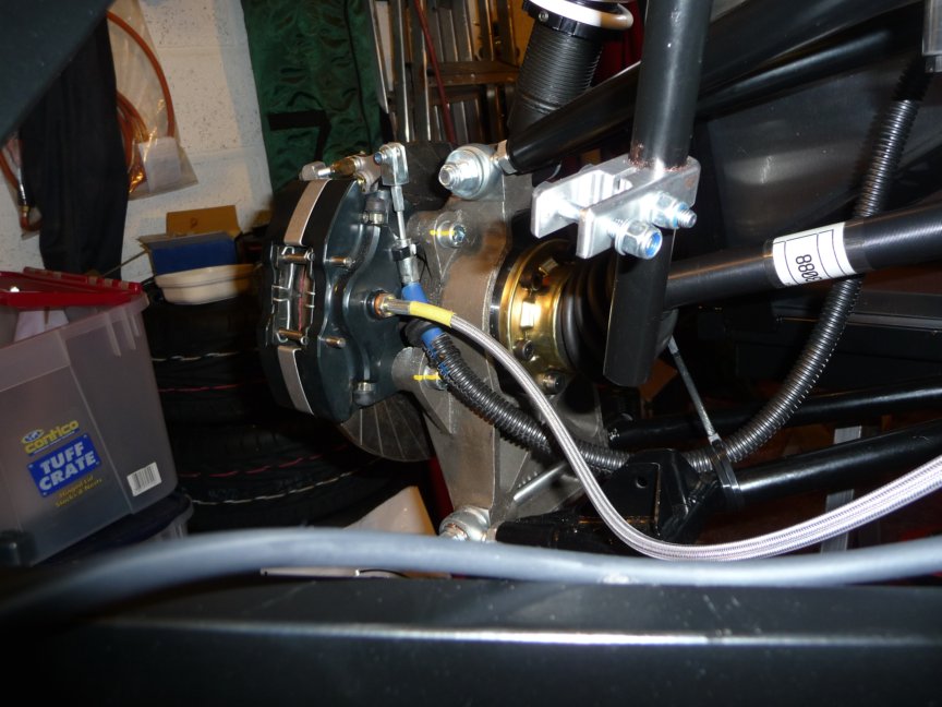
I then continued with the searing rack fitting the covers required for the IVA test, I then found I was a couple of lock nuts down (I had two larger nuts spare but not the correct ones.) so left the searing rack alone again. I then had a go at fitting the front uprights and brake units. Again the guide does not totally make it clear what is required. the ball joints come with a plastic protective covering, it does not mention these in the guide and it took a while to work at they were surplus to requirements. Also it does not mention that the top joint is tightened using a spanner and 5mm Allen key with the Allen key inserted up through the middle of the spanner. How I am going to torque these up I am yet to work out as I can't get a torque wrench on some of the nuts/bolts.
I then attached the front flexible brake hoses, this required that I remove them from the mounting points on the car first. they need to be attached to the brakes before the car.


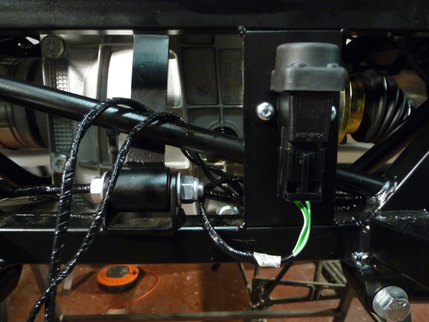
Now on to the rear uprights, checking through the parts again I realized I was missing a couple of 4" bolts. I think I was missing a couple of longer bolts for the front anti roll bar and used the ones for the rear by mistake. I decided to progress through and use a temporary bolt to attach the top of the upright. Now that the holes are the correct size for the bar it went quite smoothly, I use a trestle to support the upright while inserting the lower bar as it is quite heavy.

Once the uprights were in place and the temporary bolt (too short) was securing the top mounts I then moved on the rear anti roll bar. This again took some thought the guide says that the brackets need to be attached to the arms 121mm from the centre line from the cross bar, not 121mm down the bar but 121mm taking a parallel line. to do this I used the used the temporary table I am using which is a conti board sheet on a couple of trestles. I drew a pencil line a couple of inches from the bottom then measured 121mm from this line and drew a line parallel to it. This would be the centre line for the cross bars. The cross bar is 22mm so I then drew another two lines 11mm above and below the centre line to allow me to line the bar up easily. This worked quite well allowing me to get the brackets secured in what I hope is the correct place.

Left rear upright in place

Right rear upright in place and rear anti roll bar fitted

Once these were complete I did a little tidying up, sweeping up a few odd leaves blown in by the wind and the rivet remnants etc. I still use the other half of the garage for my car and I don't want a puncture. Oli then came back from his driving lesson and came it to have a look at progress with his instructor, Lynden. He complained that I had fitted the rear uprights as he had been working on them. I said he should have got up to help then.

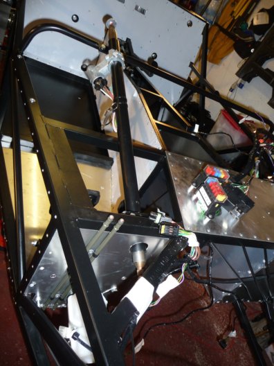
Oli trying the passenger foot brace for position

It's looking more like a car now


Build Day 11/12


Build time today 5.0 hours - Total build time 36.5 hours.
Man time today 6.0 hours - Total man time 48.5 hours.

Managed to pop into Westfield on the way home a drop off the borrowed reamer, they were closed the day before when I passed. They said that there was a fault with the wish bone and sorted out a replacement, they just need to make sure they put it back in the kit.

Only managed to spend about an hour last night doing more of the wiring loom preparatory work. Managed to get the holes drilled at the from of the chassis and down the centre tunnel then got the car turned over fully so I could tackle the rear chassis.

Spend the morning fitting a hands free kit for a friends daughter then got on with the wiring loom preparation. Completed the drilling then riveted the cable tie clips in place. Hopefully this is the last time the car will be upside down as it is starting to get heavy to turn.


We then did some work on the rear suspension re-attaching the upper wishbone and setting the rose joints. As we now have the rose joints for the anti roll bars I did some more work on the front suspension checking that tall was assembled on and attaching the bell crank to the cross brace. I will leave attaching the remaining items until it is on the ground.


Right hand side suspension


Right hand side rose joints assembled and fitted

Left hand side rose joints assembled and fitted


Foot brace placed in position.


I then worked on the passenger foot brace purchased from eBay, without modification it would not fit at the end of the foot-well, so I had to flatten out the rear section and trim and re-bend to all it to fit snugly at the end of the foot-well. I think it should do just the job.

I started to insert the rivet nuts to attach the top aluminium cover but the rivet nut tool snapped while inserting the second rivet nut, it was supplied by the same people as the first flexible drive shaft the broke on the first afternoon. I have sent them an email, will have to see what the come back with. (UPDATE the supplier has sorted me out and supplied replacement tools, thank you AB Tools)